| |
|
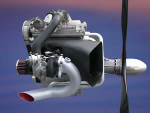
AeroTwin
Engine Features:
Crankcase
Features:
• Crankcase Material ... Aluminum Alloy
• To manage the crankcase pressure fluctuations, the motion of the
pistons is employed to do several things. First, a reed valve is attached
to the camshaft housings which are connected in turn to the crankcase.
The crankcase has, at the oil scavenge outlets, another reed valve. Upward
motion of the pistons induces air movement from the air filter, through
the camshaft housings and into the crankcase. Downward piston motion ejects
that air and the oil mixed with it into the oil reservoir. The engine
has, in effect, a dry sump pump, crankcase pressure management and internal
cooling for not only the crankcase and its contents; but also valve springs
and associated parts from piston motion only.
• Oil pressure is created by an 84mm eccentric rotor gear set driven
concentrically from the nose of the crankshaft.
• The entire crankcase and it's contents can be dismantled and removed
by undoing six nuts from studs that clamp the crankcase to the cylinder
head and barrel casting. All connecting metal surfaces are furnished with
o-ring seals so that no sealant of any kind is required at assembly. Oil
is transported to the cylinder head via drillings through the centres
of the crankcase studs. As the barrels and cylinder head are cast as one,
headgaskets and the accompanying studs and nuts are not required, this
offers complete freedom in the choice of valve angle, valve length and
port disposition.
Electrical
Features:
• One coil assembly comprising four coils fires sequentially.
• Two crankangle sensors, one to record crankshaft position; the
other, camshaft position.
• The starting mechanism comprises a sealed starter driving a gear
cascade to an inertia gear set, which in turn engages with a ring gear
mounted between the cylinders inside the crankcase on the crankshaft,
mounted as part of the counterweighting. The drive ratio of the starting
mechanism is structured so as to provide for 72 teeth on the ring gear,
which when read by the crank angle sensor offers timing resolution equal
to 5° or better, and can thus be used for both injection and ignition
timing angle calibrations.
• The ECU, charging system rectifier and ignition drives are all
mounted on the engine to greatly reduce the bulk of the wiring loom. This
has the added benefit of limiting EMF propagation and susceptibility and
leaves the owner with virtually one plug to wire the engine into it's
work environment.
Electrical Fuel Injection:
• Dynamic fuel and ignition settings are determined by an air pressure
transducer which indicates to the ECU the load the engine is experiencing.
In conjunction with air temperature and cylinder head temperature sensors;
the ECU compensates for altitude, engine load, variables in air temperature,
and overall engine temperature.
Cooling
System:
• Engine is designed to have all air in-take from one side of the
engine and all exhaust and heat rejection on the other side. This creates
a natural cooling flow of air across the engine.
• Cooling system is fed by propeller wash.
• Ceramic coating is used on the combustion chamber to reduce temperature
transfer into piston, head and cylinder walls. This results in more heat
removed with the exhaust for greater reduction of overall engine temperature.
NEW! 3/29/06:
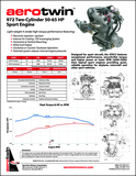
AeroTwin Features & Specifications Sheet (PDF 4.2M)
NEW! 2/20/06:
Installation
Details (Fixed Wing Interface) PDF format
Installation
Details (Rotary Wing Interface) PDF format
U.S. and International Patents Pending.
|
|